Imagine 10 Gbps on a Single Copper Pair: How Is That Technically Possible?

Introduction: Breaking the Copper Speed Myth

For decades, copper cabling has been considered fundamentally limited compared to optical fiber. As data rates climbed from 100 Mbps to 1 Gbps and then to 10 Gbps, the number of copper pairs, cable thickness, power consumption, and signal-processing complexity all increased dramatically. The prevailing assumption became simple: very high data rates require either many copper pairs or fiber.

Yet recent developments challenge that assumption. Achieving 10 Gbps full-duplex over a single copper pair is not only theoretically possible but practically achievable over short distances. The IEEE 802.3ch-2020 standard defines 10GBASE-T1, which delivers 10 Gbps over a maximum distance of 15 meters with up to four in-line connectors—specifically designed for automotive backbone networks, high-resolution ADAS camera links, and industrial automation.

This raises an important question: how can such a narrow physical medium support such extreme throughput?

The answer lies in a combination of advanced modulation schemes, aggressive signal processing, full-duplex echo cancellation, and the exploitation of higher-frequency spectra than traditionally used in Ethernet. Importantly, this is not a single breakthrough, but rather the convergence of techniques that have matured across Ethernet, DSL, and high-speed serial links.

This article explores the engineering foundations behind 10 Gbps over a single copper pair, focusing on physical-layer mechanisms, trade-offs, and real-world constraints. The target audience is engineers familiar with digital communications, Ethernet PHYs, or high-speed signaling.

Why Copper Is Hard: Fundamental Physical Constraints

Copper transmission lines are governed by several well-known impairments that worsen rapidly with frequency and distance:

Frequency-Dependent Attenuation

Skin effect causes signal attenuation to increase approximately with the square root of frequency. At 4 GHz (required for 10GBASE-T1), skin depth in copper is only approximately 1 micrometer, forcing current to the conductor surface and dramatically increasing resistance. This is why cable gauge and conductor quality critically impact 10GBASE-T1 performance; poor conductors cannot support 15 meters at these frequencies.

At several hundred MHz or above, insertion loss becomes severe, especially on thin conductors. Unlike traditional Ethernet, which can use unshielded twisted-pair (UTP) cabling, 10GBASE-T1 requires shielded cabling to maintain signal integrity at multi-GHz frequencies.

Crosstalk

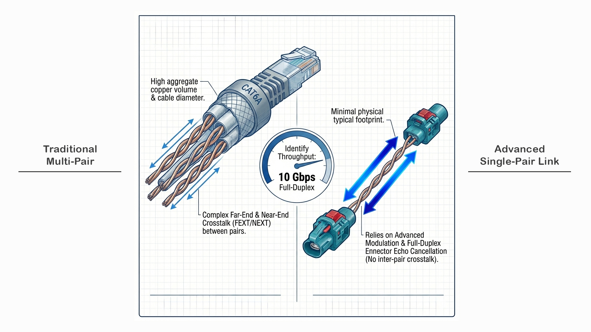
In multi-pair cables like traditional 10GBASE-T, near-end and far-end crosstalk (NEXT/FEXT) between the four twisted pairs dominate system design, compounded by alien crosstalk from neighboring cables in bundles.

Single-pair Ethernet (10GBASE-T1) eliminates internal pair-to-pair crosstalk entirely since only one pair exists—there are no other pairs within the cable to couple with. However, shielded cabling is still required to mitigate alien crosstalk from adjacent cables in automotive harnesses and to protect against external electromagnetic interference (EMI). This is a significant simplification compared to multi-pair systems, but it doesn't eliminate all crosstalk concerns.

Reflections and Impedance Mismatch

10GBASE-T1 requires precisely controlled 100Ω differential impedance. Connectors (up to four allowed per 15-meter link), splices, and PCB transitions introduce impedance discontinuities, causing reflections that distort symbols and reduce eye openings. This is especially critical at multi-GHz frequencies, where even small impedance variations (±5Ω) can cause significant signal-integrity issues.

The standard specifies stringent return loss requirements across the entire 4 GHz bandwidth to ensure reflections remain manageable.

Noise Sources

Thermal noise, impulse noise, and external RF coupling all degrade signal-to-noise ratio (SNR). As data rates increase, required SNR margins become increasingly tight. 10GBASE-T1 operates with SNR margins around 20 dB, requiring aggressive equalization and forward error correction to maintain reliable operation.

The Bandwidth Trade-off: Why Single-Pair Needs 8× More Frequency

This is the fundamental engineering trade-off that makes single-pair 10 Gbps both impressive and challenging.

Traditional 10GBASE-T (Four-Pair Strategy)

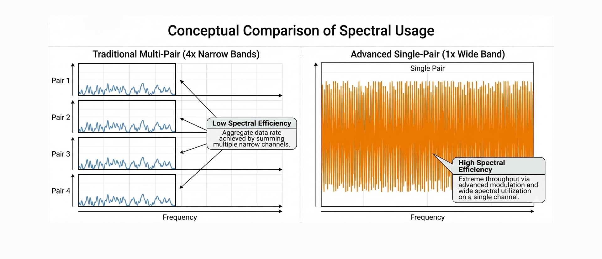
Traditional 10GBASE-T achieves 10 Gbps by splitting the load across four pairs:

  • 4 pairs × 2.5 Gbps each = 10 Gbps total
  • Each pair operates at 800 Mbaud
  • Uses DSQ128 (Double-Square 128-point constellation), a sophisticated two-dimensional modulation based on 16-level PAM with Tomlinson-Harashima precoding
  • Effectively transmits ~4 bits per symbol per dimension
  • Frequency bandwidth: ~500 MHz per pair
  • Distance: 100 meters over Category 6A UTP cable

Single-Pair 10GBASE-T1 (All on One Pair)

Single-pair 10GBASE-T1 must carry all 10 Gbps on one conductor pair:

  • 1 pair × 10 Gbps (no load sharing possible)
  • Operates at ~3.125 Gbaud (much higher symbol rate)
  • Uses PAM-4 (4-level pulse amplitude modulation)
  • Transmits 2 bits per symbol
  • Frequency bandwidth: ~4 GHz (eight times higher!)
  • Distance: 15 meters over shielded twisted pair

Why PAM-4 Instead of Higher-Order Modulation?

You might ask: why not use PAM-16 or PAM-32 to pack more bits per symbol and reduce bandwidth requirements?

The answer is noise margin. At 4 GHz over copper:

  • Channel attenuation is severe (>40 dB at 15m)
  • Noise levels are high
  • Available SNR limits practical modulation order

PAM-4 provides the best balance:

  • Only 2 bits/symbol means larger voltage spacing between levels
  • Better noise immunity at extreme frequencies
  • Still requires sophisticated DSP, but remains implementable

Higher-order modulation (PAM-8, PAM-16) would demand impractically high SNR at these frequencies and distances.

The Engineering Implication

This massive frequency increase (500 MHz → 4 GHz) is only practical because:

  • Distance is limited to 15 meters (vs. 100m for 10GBASE-T)
  • Shielded cable is mandatory (vs. optional UTP for 10GBASE-T)
  • Automotive environment tolerates higher cost/complexity for harness weight and connector count savings
  • Short reach makes cable attenuation manageable despite extreme frequencies

Why Two-Wire Ethernet Matters for Automotive

Before diving deeper into the 10 Gbps implementation, it's important to understand why the automotive industry invested heavily in single-pair Ethernet.

The Harness Weight Problem

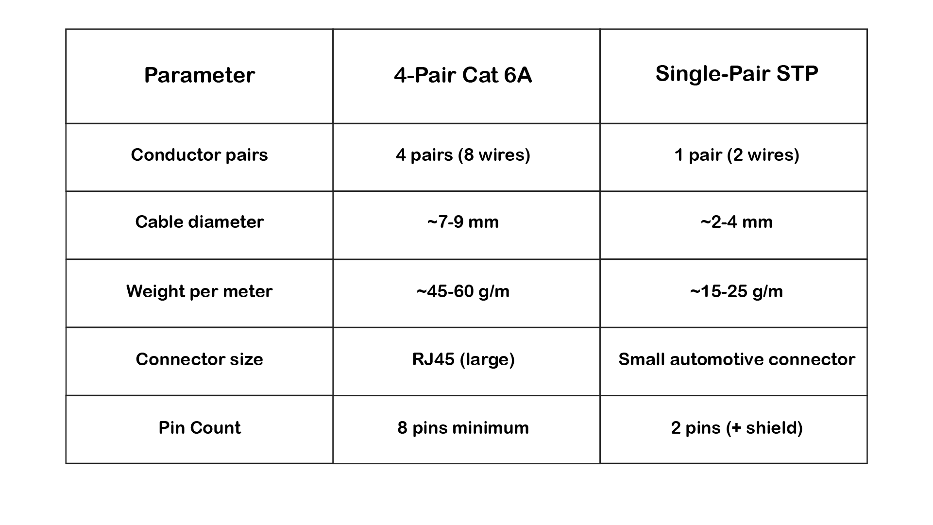
Modern vehicles contain kilometers of wiring:

  • Premium vehicles: 2-4 km of cable
  • Electric vehicles: 3-5 km of cable
  • Autonomous vehicles (future): 5+ km projected

Weight impact:

  • Traditional wiring harness: 40-60 kg
  • Each kg of weight reduces EV range by ~0.1%
  • For EVs: Every kilogram matters for efficiency

Single-pair vs. Four-pair comparison:

Example calculation:

  • 50 meters of backbone cabling in vehicle
  • 4-pair cable: 50m × 50g/m = 2.5 kg
  • Single-pair: 50m × 20g/m = 1.0 kg
  • Savings: 1.5 kg per link

Multiply by dozens of high-speed links → significant total savings.

The Connector Real Estate Problem

Dashboard, door modules, and zonal ECUs are space-constrained. Large RJ45 connectors don't fit.

Single-pair automotive connectors:

  • MATEnet (TE Connectivity): Compact design
  • ix Industrial (Hirose): Rugged, sealed
  • Custom OEM connectors: Optimized per application

These are 3-5× smaller than RJ45 and designed for:

  • Vibration resistance (automotive requirement)
  • Temperature extremes (-40°C to +125°C)
  • IP67 or IP68 sealing (water/dust)
  • Tool-free or simplified assembly

The Cost Structure

Counter-intuitively, single-pair can be more expensive per meter due to:

  • Shielding requirements (mandatory for GHz operation)
  • Higher-quality conductors (skin effect at 4 GHz)
  • Tighter impedance control (100Ω ±5Ω)

But total system cost is lower:

  • Fewer connectors needed
  • Simpler routing (thinner cables)
  • Reduced assembly labor (fewer pins to terminate)
  • Less harness design complexity
  • Fewer switch ports required (one port = one link, not trunk of 4-pair)

Two-Wire Enables Zonal Architecture

Modern vehicles are transitioning from domain-based to zonal-based electrical architectures:

Old Domain Architecture:

  • Separate ECUs for: powertrain, body, chassis, ADAS, infotainment
  • Star topology: every ECU connects to central gateway
  • Result: cable runs across entire vehicle

New Zonal Architecture:

  • Vehicle divided into physical zones (front-left, front-right, rear, etc.)
  • One zonal controller per zone aggregates local sensors/actuators
  • Zonal controllers connect to central compute via high-speed backbone

This requires:

  • High bandwidth between zonal controllers (10GBASE-T1)
  • Short distances (zones are physically close)
  • Low weight/complexity per link

Single-pair 10GBASE-T1 is purpose-built for this architecture:

  • 10 Gbps sufficient for aggregated zone traffic
  • 15m reaches across vehicle zones
  • Minimal harness weight penalty
  • Simplified switch topologies

Comparison: Why Not Just Use Fiber?

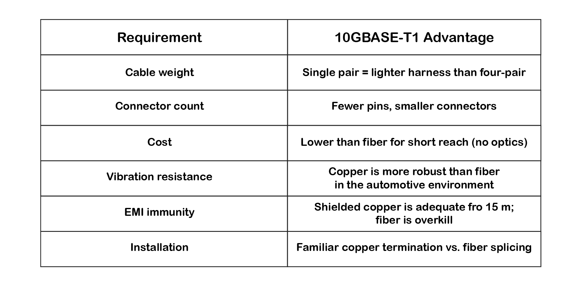
Valid question. Fiber has advantages (no EMI, theoretically unlimited bandwidth), but:

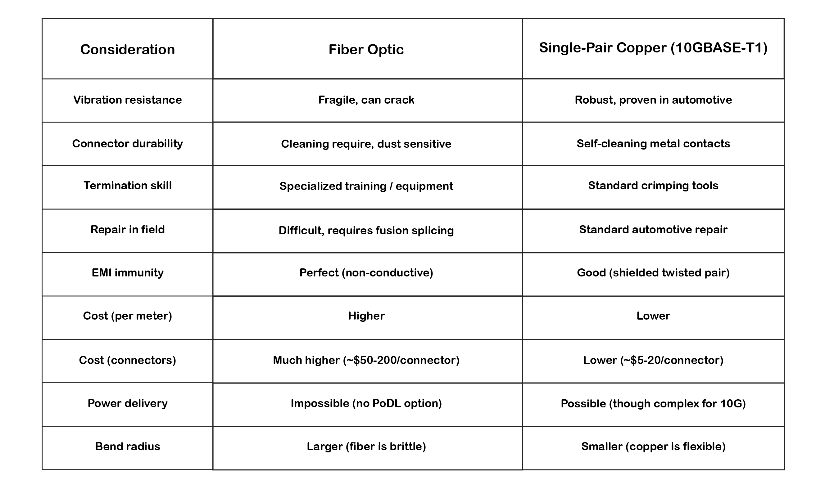
For 15-meter automotive applications, copper wins on:

  • Mechanical robustness
  • Serviceability
  • Familiarity with technicians
  • Total cost of ownership

Fiber makes sense for:

  • Extremely long runs (>100m) where copper attenuation too high
  • Extreme EMI environments (near high-power inverters)
  • Future >10 Gbps requirements

For the bulk of automotive high-speed networking, two-wire copper Ethernet hits the sweet spot.

At its core, data rate is governed by the Shannon-Hartley theorem:

C = B · log₂(1 + SNR)

Where:

  • C is channel capacity (bits/second)
  • B is bandwidth (Hz)
  • SNR is signal-to-noise ratio (linear, not dB)

For 10GBASE-T1, achieving 10 Gbps capacity over 15 meters requires:

  • B ≈ 4 GHz (bandwidth)
  • SNR > 100:1 linear (>20 dB) after equalization
  • This explains why PAM-4 (not PAM-16) is used—higher-order modulation would demand impractically high SNR at these frequencies

For a single copper pair, increasing capacity requires one or more of the following:

  • Increase bandwidth (4 GHz for 10GBASE-T1)
  • Increase SNR (through equalization and shielding)
  • Increase bits per symbol (PAM-4 chosen as optimal)

In practice, all three are used simultaneously.

Exploiting Higher Frequencies

Traditional Ethernet was limited to relatively conservative frequency ranges to ensure robustness and compatibility. 10GBASE-T operates up to 500 MHz across four pairs. Single-pair 10GBASE-T1, however, must compress the entire 10 Gbps onto one pair, requiring bandwidth extension to approximately 4 GHz—eight times higher than multi-pair 10GBASE-T.

This dramatic frequency increase is only feasible over the short 15-meter automotive distances where attenuation remains manageable and sophisticated DSP can compensate for channel impairments.

The Two-Wire Ethernet Evolution

The journey to 10GBASE-T1 didn't happen overnight. Single-pair Ethernet evolved through several generations, each pushing the frequency and complexity envelope:

But it all started with a vision.

The Origin Story: 2011 - When Automotive Giants Saw the Future

In 2011, something remarkable happened in the automotive world. Volvo Technology and BMW independently came to the same conclusion: Ethernet is the future of in-vehicle networks.

At the time, this was controversial. The automotive industry had spent decades perfecting CAN and FlexRay. Why risk disrupting proven technologies?

The answer was data.

Emerging ADAS systems, high-definition cameras, and the early vision of autonomous driving made it clear: CAN's 1 Mbps and even FlexRay's 10 Mbps would not scale. The industry needed 100× to 1000× more bandwidth, and traditional automotive protocols couldn't deliver.

November 2011: The OPEN Alliance is Born

Industry leaders recognized they couldn't solve this alone. In November 2011, the OPEN Alliance Special Interest Group was formed with a singular mission: speed up the adoption of Ethernet in automotive in-vehicle networks.

The founding members included:

  • BMW
  • Broadcom
  • Freescale (now NXP)
  • Harman
  • Hyundai
  • NXP
  • Volkswagen

Their goal was ambitious: adapt commercial Ethernet technology for the harsh realities of automotive environments, vibration, temperature extremes, EMI, cost constraints, and weight limitations.

Real-World Pioneers: Volvo's Brake-by-Wire on Ethernet

One of the earliest real-world implementations came from Volvo Technology. They embarked on an ambitious project: implementing brake-by-wire over Ethernet.

This wasn't just about data logging or infotainment. This was safety-critical, real-time vehicle control over a network technology the automotive world had never used for such applications.

The challenge:

  • Brake commands require deterministic latency (<10 ms)
  • Functional safety (ISO 26262) demanded unprecedented reliability
  • EMI from ABS motors and high-current braking systems
  • Temperature extremes in wheel wells and engine compartment
  • Vibration and mechanical stress on connectors

The team needed partners who understood both automotive requirements and Ethernet technology. This is where companies like the founder's previous company came in, working as members of Volvo's groundbreaking project.

Why this mattered: Brake-by-wire on Ethernet proved that Ethernet wasn't just for infotainment or diagnostics. It could handle the most demanding, safety-critical automotive applications, paving the way for steer-by-wire, throttle-by-wire, and eventually full drive-by-wire systems.

The lessons learned from this project directly influenced:

  • IEEE 802.1 AVB/TSN standards (time-sensitive networking)
  • Physical layer requirements for automotive Ethernet
  • Functional safety profiles for Ethernet in safety-critical systems
  • The realization that single-pair copper was essential for weight/cost

The Technical Evolution Timeline

Armed with these early learnings, the industry embarked on a systematic evolution:

100BASE-T1 (2015 - IEEE 802.3bw):

  • Speed: 100 Mbps full-duplex
  • Distance: Up to 15 meters (automotive), 40+ meters (industrial)
  • Modulation: PAM-3 (3-level)
  • Frequency: ~30-100 MHz
  • Use case: Camera links, sensor connections in vehicles

1000BASE-T1 (2016 - IEEE 802.3bp):

  • Speed: 1 Gbps full-duplex
  • Distance: Up to 15 meters (Type A) or 40 meters (Type B)
  • Modulation: PAM-3
  • Frequency: ~600 MHz
  • Use case: ECU backbone, high-bandwidth sensors

2.5GBASE-T1 / 5GBASE-T1 (2020 - IEEE 802.3ch):

  • Speed: 2.5 Gbps or 5 Gbps full-duplex
  • Distance: 15 meters
  • Modulation: PAM-4
  • Frequency: ~1 GHz (2.5G), ~2 GHz (5G)
  • Use case: Multi-camera systems, zonal architectures

10GBASE-T1 (2020 - IEEE 802.3ch):

  • Speed: 10 Gbps full-duplex
  • Distance: 15 meters
  • Modulation: PAM-4
  • Frequency: ~4 GHz
  • Use case: Centralized compute platforms, lidar arrays, backbone switches

Key Pattern: Each speed increase brought:

  • Higher frequency operation (100 MHz → 4 GHz progression)
  • More sophisticated modulation (PAM-3 → PAM-4)
  • More aggressive DSP requirements
  • Maintained the 15m automotive distance constraint

This shows a systematic evolution in which lessons from 100BASE-T1 and 1000BASE-T1 deployments informed the design of 10GBASE-T1. The automotive industry created a family of compatible two-wire Ethernet technologies, each scaled for different bandwidth requirements.

Short Reach Changes Everything

A key design decision for automotive Single-Pair Ethernet was to standardize on a maximum length of 15 metersfor high-speed variants (1G, 2.5G, 5G, 10G). This wasn't arbitrary, it reflects real automotive architecture:

Typical vehicle cable runs:

  • Front camera to central ECU: 5-8 meters
  • Rear camera to central ECU: 8-12 meters
  • Zonal controller to domain controller: 3-10 meters
  • Door modules to body controller: 2-5 meters

Why 15m is the sweet spot:

  • Covers 95%+ of in-vehicle connections
  • Short enough that attenuation is manageable at GHz frequencies
  • Allows realistic SNR targets for PAM-4 modulation
  • Permits aggressive frequency reuse (4 GHz viable)
  • Keeps cable cost per meter acceptable (shielded STP required)

Over these distances:

  • Attenuation is manageable (~40-50 dB at 4 GHz vs. >100 dB at 100m)
  • Reflections can be equalized with practical DSP complexity
  • EMI pickup is reduced compared to long runs (exposure time limited)
  • Power budgets are more forgiving (PHY can dissipate 2-4W)
  • Installation and termination remain practical

Compared to traditional Ethernet distance targets:

  • 10BASE-T: 100 meters
  • 100BASE-TX: 100 meters
  • 1000BASE-T: 100 meters
  • 10GBASE-T: 100 meters

Automotive Ethernet inverted the priority: Instead of maximizing distance, it maximized data density (Gbps per wire pair) within the distances that actually matter for vehicles and industrial machines.

This makes high-frequency copper transmission far more realistic than attempting similar speeds over 100-meter office/datacenter distances.

Modulation: Packing More Bits per Symbol

Once bandwidth is extended to 4 GHz, the next lever is modulation efficiency.

From Binary to Multi-Level Signaling

Early Ethernet used simple binary signaling (NRZ: Non-Return-to-Zero). Modern systems rely on Pulse Amplitude Modulation (PAM), where each symbol represents multiple bits.

Common PAM schemes:

  • PAM-2 (Binary) → 1 bit/symbol
  • PAM-4 → 2 bits/symbol (used in 10GBASE-T1)
  • PAM-8 → 3 bits/symbol
  • PAM-16 → 4 bits/symbol

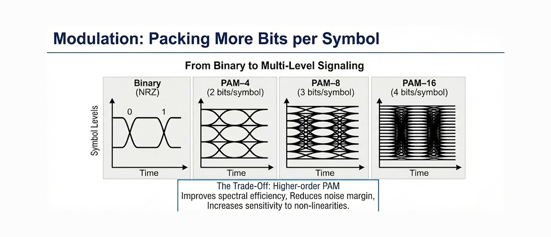
10GBASE-T1 uses PAM-4 specifically because:

  1. At 4 GHz over 15m copper, SNR is limited
  2. PAM-4's four voltage levels provide adequate noise margin
  3. Higher-order PAM would require SNR that's unachievable without impractical complexity
  4. 2 bits/symbol at ~3.125 Gbaud = ~10 Gbps effective (with FEC overhead)

The Trade-Off

Higher-order PAM:

  • Improves spectral efficiency (more bits per Hz)
  • Reduces noise margin (levels are closer together)
  • Increases sensitivity to non-linearities (requires more linear amplifiers)
  • Demands higher SNR

For 10GBASE-T1, the decision to use PAM-4 rather than PAM-8 or PAM-16 reflects the practical SNR limits at 4 GHz over copper. As a result, advanced DSP is required to reliably recover signals, even with the "conservative" PAM-4 choice

Full-Duplex on a Single Pair: Echo Cancellation

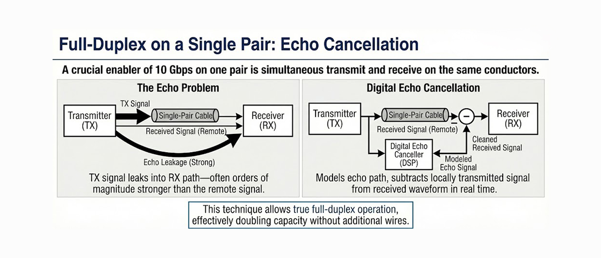
A crucial enabler of 10 Gbps over a single pair is simultaneous transmit and receive on the same conductors—true full-duplex operation.

The Echo Problem

When transmitting and receiving concurrently on a single pair, the transmitted signal leaks into the receiver path—often 60-80 dB stronger than the remote signal. This "near-end echo" would completely swamp the desired signal without mitigation.

Imagine trying to hear a whisper while shouting into a megaphone—that's the scale of the problem.

Digital Echo Cancellation

Modern PHYs solve this by:

01. Modeling the echo path digitally

- Characterizes how the transmit signal couples into the receiver

- Accounts for hybrid circuit imperfections

- Models reflections from impedance mismatches

02. Continuously subtracting the locally transmitted signal from the received waveform

- Creates a replica of the echo

- Subtracts it in the digital domain with high precision

- Reveals the much weaker remote signal underneath

03. Adapting in real time to temperature, aging, and impedance changes

- Echo path changes with temperature (cable resistance varies)

- Adaptive algorithms continuously update coefficients

- Handles connector variations and aging effects

This technique, pioneered in DSL (Digital Subscriber Line) and perfected in multi-gigabit Ethernet, allows true full-duplex operation, effectively doubling capacity without additional wires.

For 10GBASE-T1:

  • Echo cancellation must suppress 60-80 dB of echo
  • Operates at 3+ Gbaud symbol rates
  • Adapts continuously during operation
  • Critical to achieving 10 Gbps full-duplex on one pair

Without echo cancellation, you would need separate transmit and receive pairs (half-duplex or separate pairs), doubling cable complexity.

Equalization: Undoing the Damage

At multi-GHz symbol rates, copper channels behave like severe low-pass filters with frequency-dependent phase distortion. At 4 GHz, a 15-meter cable can exhibit 40-50 dB of attenuation, essentially obliterating high-frequency components.

Transmitter Pre-Emphasis

The transmitter intentionally boosts high-frequency components (pre-distortion) so that, after channel attenuation, the received spectrum is approximately flat.

Example:

  • If the channel attenuates 4 GHz signals by 45 dB more than DC
  • Transmitter boosts 4 GHz components by +45 dB (within power limits)
  • After cable, all frequencies arrive at similar levels

This is analogous to shouting louder at high pitches so that, after traveling through walls, all pitches are equally audible.

Receiver Equalization

Multiple equalization stages are commonly used in cascade:

01. Continuous-Time Linear Equalizer (CTLE)

- Analog equalizer in the receiver front-end

- Boosts high frequencies before ADC

- Improves ADC dynamic range

02. Feed-Forward Equalizer (FFE)


- Digital FIR filter

- Removes pre-cursor intersymbol interference (ISI)

- Typically 10-30 taps for 10GBASE-T1

03. Decision-Feedback Equalizer (DFE)


- Uses previously detected symbols to cancel post-cursor ISI

- Highly effective but sensitive to error propagation

- Typically 5-15 taps

These work together to:

  • Mitigate intersymbol interference (ISI)
  • Flatten frequency response
  • Compensate for group delay distortion
  • Remove echoes and reflections

Adaptive DSP

Modern PHYs continuously adapt equalization coefficients based on channel conditions using algorithms like:

  • Least Mean Squares (LMS)
  • Recursive Least Squares (RLS)

This enables stable operation even on:

  • Imperfect cabling with variations
  • Temperature changes (-40°C to +125°C automotive range)
  • Aging effects over the vehicle lifetime
  • Different connector configurations (0 to 4 connectors allowed)

The result: A channel that would be completely unusable without equalization becomes capable of reliable 10 Gbps transmission.

Forward Error Correction: Embracing Imperfection

At extreme data rates over challenging channels, achieving a perfectly clean signal is unrealistic. Instead, systems rely on Forward Error Correction (FEC) to tolerate a certain level of residual errors.

Why FEC Is Essential

Even after aggressive equalization:

  • Some symbols will be incorrectly decoded
  • PAM-4 at 4 GHz over copper has a limited noise margin
  • Raw bit error rate (BER) might be 10⁻⁴ to 10⁻⁶
  • Applications require BER < 10⁻¹² for reliable operation

FEC allows operation closer to Shannon limits by correcting residual bit errors after detection.

Typical Approaches for 10GBASE-T1

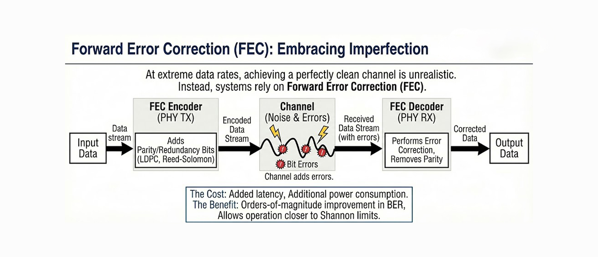
LDPC (Low-Density Parity Check) codes:

  • Extremely efficient near Shannon limit
  • Moderate complexity for hardware implementation
  • Used in many modern standards (10GBASE-T, Wi-Fi 6, 5G)

RS-FEC (Reed-Solomon):

  • Alternative used in some implementations
  • Well-understood and proven

The cost of FEC:

  • Added latency (encoding/decoding delay: typically 1-2 µs)
  • Additional power consumption (FEC engines require silicon area and power)
  • Bandwidth overhead (10-15% redundancy added)

The benefit:

  • Orders-of-magnitude improvement in BER (10⁻⁴ raw → 10⁻¹² corrected)
  • Enables operation in marginal SNR conditions
  • Provides margin for aging and temperature extremes

Practical example:

  • Without FEC: 10⁻⁴ BER = 1 error per 10,000 bits = 1 million errors/second at 10 Gbps
  • With FEC: 10⁻¹² BER = 1 error per trillion bits = 1 error per 100 seconds
  • This makes the difference between unusable and production-quality link

Power Delivery and Thermal Constraints

A less obvious challenge is power consumption and heat dissipation.

DSP Is Power-Hungry

High-speed ADCs, DACs, and DSP blocks required for 10GBASE-T1 consume significant power:

  • Multi-Gsps ADC/DAC: 500 mW to 1 W each
  • Echo cancellation engine: 500 mW to 1 W
  • Equalization (FFE/DFE): 300-500 mW
  • FEC encoder/decoder: 200-400 mW
  • PHY control and clocking: 200-300 mW

Total PHY power consumption: Typically 2-4 watts per port

This generates substantial heat that must be managed, especially in:

  • Compact automotive ECUs with limited airflow
  • Industrial environments with high ambient temperatures
  • Multi-port switches in confined spaces

Thermal management strategies:

  • Heat sinks or thermal pads on PHY chips
  • PCB copper pour for heat spreading
  • Careful component placement for airflow
  • Power management modes during idle periods

Power over Data Lines (PoDL) in Automotive

Power over Data Lines (PoDL) is standardized and proven for lower-speed Single Pair Ethernet variants (10BASE-T1L, 100BASE-T1, 1000BASE-T1) under IEEE 802.3bu. However, for 10GBASE-T1, PoDL adoption faces technical and systemic challenges rather than technological immaturity:

Technical Considerations:

  1. Magnetics complexity
    • Coupling DC power with 4 GHz AC signals requires a sophisticated transformer design
    • Common-mode chokes must handle both DC current and multi-GHz differential signals
    • Parasitic capacitance and inductance become critical
  2. EMC (Electromagnetic Compatibility)
    • Injecting DC power over long, unshielded SPE links increases radiated emissions
    • Common-mode noise from power injection can degrade signal integrity
    • Additional filtering and isolation required
    • More extensive EMC validation testing
  3. Thermal management
    • 10GBASE-T1 PHYs already dissipate 2-4W
    • Adding PoDL power (upto 30W @ 24V for powered devices)
    • Total heat in connectors/magnetics can exceed thermal limits
    • Cable heating from combined data + power current

Systemic Factors:

  1. Existing power infrastructure
    • Vehicles already have robust 12V / 48V distribution networks
    • Adding PoDL creates parallel power domains
    • Limited benefit when power is already available nearby
  2. Functional safety & fault isolation (ISO 26262)
    • Power + data on the same pair complicates fault detection:
      • Short circuit detection and isolation
      • Safe shutdown procedures during faults
    • Extensive FMEA (Failure Modes and Effects Analysis) required
  3. OPEN Alliance system profiles
    • OPEN Alliance (automotive Ethernet consortium) has not yet defined official system profiles for 10GBASE-T1 + PoDL
    • OEMs typically wait for industry consensus before adoption
    • Lack of standard profiles reduces supplier ecosystem support
  4. Tooling & debug complexity
    • Engineers want visibility and control during development
    • PoDL obscures power behavior inside PHY + coupling networks
    • Harder to measure and troubleshoot power issues
    • Requires specialized test equipment

Where PoDL Makes Sense

Despite challenges, PoDL remains viable and beneficial for specific 10GBASE-T1 applications like Remote ADAS cameras, where running separate power is difficult.

And PoDL is viable in 1000BASE-T1 applications like:

  • Sensors in hard-to-reach locations (roof-mounted lidar, bumper radars)
  • Simplified harness designs where reducing wire count matters
  • Retrofit scenarios using existing single-pair infrastructure

For backbone ECU-to-ECU links, separate power delivery typically remains the pragmatic choice.

Where 10GBASE-T1 Makes Sense

Single-pair 10 Gbps is not a universal replacement for fiber or traditional multi-pair Ethernet. It excels in specific scenarios where its unique characteristics provide clear advantages:

Primary Applications:

Automotive Backbone Networks:

  • Zonal architecture backbones connecting domain controllers
  • High-resolution ADAS cameras (8MP, 12MP, and beyond)
  • Lidar sensor arrays requiring multi-Gbps data rates
  • Centralized computing platforms in autonomous vehicles
  • Replacing multiple lower-speed links with a single high-speed connection

Industrial Automation:

  • Robotics control systems requiring deterministic low-latency
  • Machine vision systems with high-resolution cameras
  • Factory automation backbones
  • Harsh environment applications (vibration, temperature extremes)

Embedded and Edge Computing:

  • High-speed sensor aggregation
  • Edge AI compute nodes
  • Data acquisition systems

Not Suitable For:

  • Long-distance data center links (use fiber - lower loss, no EMI)
  • Office networking beyond 15m (use standard 10GBASE-T over Cat 6A)
  • Cost-sensitive consumer applications (complexity drives up cost)
  • Applications requiring >15m reach (physical limitation of standard)

In environments where cable weight, connector count, harsh-environment resistance, and cost matter more than maximum distance, 10GBASE-T1 offers compelling advantages.

Future Outlook: The Two-Wire Ethernet Roadmap

As CMOS process nodes advance and DSP efficiency increases, the feasibility of ultra-high-speed copper links continues to expand. What once required laboratory-grade equipment and expertise is increasingly becoming produceable silicon available to automotive Tier 1 suppliers.

Emerging Trends in Single-Pair Ethernet:

Beyond 10 Gbps on Two Wires:

  • 25GBASE-T1 under research (IEEE exploration)
    • Target: 25 Gbps over 5-10 meters
    • Improved Support of Asymmetric Applications for MGbps Ethernet Cameras (ISAAC)
    • Challenge: 8-10 GHz bandwidth requirement
    • Use case: Direct GPU-to-sensor links in compute platforms
  • Bonded pairs (2 × 10GBASE-T1 = 20 Gbps)
    • Two single-pairs in parallel
    • Still lighter/simpler than traditional four-pair
    • Emerging for ultra-high-resolution cameras (16K, uncompressed video)

Lower-speed variants continuing to proliferate:

  • 10BASE-T1S (IEEE 802.3cg): 10 Mbps, multi-drop bus topology
    • Replaces CAN/LIN for simple sensors
    • Same two-wire infrastructure philosophy
  • 100BASE-T1 adoption accelerating
    • Becoming standard for mid-tier cameras and sensors
    • Proven reliability after years of deployment

Integration and power reduction:

  • System-on-chip integration (MAC + PHY + switch fabric)
    • Complete Ethernet switch with 10GBASE-T1 ports on a single chip
    • Reduces board space and power
  • Advanced process nodes (7nm, 5nm), reducing PHY power consumption
    • Current: 2-4W per 10GBASE-T1 port
    • Target: <2W per port for next-generation PHYs
  • Better thermal management allows higher port density
    • Multi-port switches with 8-16 × 10GBASE-T1 ports
    • Automotive-grade thermal design

Standardization Evolution:

IEEE 802.3 ongoing work:

  • Refining 10GBASE-T1 interoperability requirements
  • Developing test methodologies for automotive compliance
  • Exploring >10G variants

OPEN Alliance (automotive consortium):

  • Defining system-level profiles for 10GBASE-T1
  • Certification programs ensuring multi-vendor interoperability
  • Test specifications for automotive environmental validation
  • Potential future work on 10GBASE-T1 + PoDL profiles

Broader ecosystem development:

  • More PHY chip vendors entering the market (competition drives cost down)
  • Standardized connector families from multiple suppliers
  • Test equipment ecosystem (oscilloscopes, traffic generators, compliance testers)
  • Growing base of field-proven deployments

Automotive Architecture Evolution Driving Two-Wire Adoption:

Zonal architectures and Software-defined vehicles are becoming mainstream:

  • Every major OEM is planning zonal migration (2024-2028 timeframe)
  • Creates an immediate need for 10GBASE-T1 backbone links
  • Projected: 5-10 × 10GBASE-T1 links per vehicle by 2028
  • Traditional ECUs → thin edge nodes + powerful central computer
  • Central computer needs high-speed aggregation (10G × multiple zones)
  • OTA updates require high-bandwidth distribution
  • Two-wire 10GBASE-T1 enables hub-and-spoke topology

Sensor fusion requiring aggregation of multi-Gbps streams:

  • ADAS Level 3+ requires 10+ cameras + radars + lidars
  • Camera resolution increasing (4MP → 8MP → 12MP → 16MP)
  • Uncompressed or lightly-compressed video for AI processing
  • Example bandwidth requirement:
    • 12MP camera @ 30fps, 12-bit color ≈ 8.6 Gbps raw
    • Four such cameras → 34 Gbps aggregate
    • Requires multiple 10GBASE-T1 links or bonded pairs

The Two-Wire Ecosystem Maturity:

2015-2018: Early adoption (100BASE-T1, 1000BASE-T1)

  • Tier 1 suppliers developing first products
  • Limited PHY chip availability (primarily Broadcom, Marvell)
  • Custom connectors, no standardization
  • High cost per port

2019-2022: Volume production (1000BASE-T1 mainstream)

  • Multiple PHY vendors (NXP, TI, Microchip join the market)
  • Standardized connectors (MATEnet, ix Industrial)
  • Cost reduction through volume
  • Proven reliability in the field

2023-2025: Multi-gigabit transition (2.5G/5G/10GBASE-T1)

  • 10GBASE-T1 entering production vehicles
  • Switch chips with integrated MultiGBASE-T1 ports
  • Automotive OEMs specifying for next-generation platforms
  • Cost approaching viability for mass-market vehicles

2026-2030: Widespread deployment (projected)

  • 10GBASE-T1 standard in premium and EV segments
  • Filtering down to mid-tier vehicles
  • Established multi-vendor ecosystem
  • Mature tooling and validation processes

Long-term Trajectory:

The boundary between copper and fiber will continue to blur, especially for short-reach applications where copper's mechanical simplicity, robustness, and familiarity offer compelling advantages over the theoretical superiority of optics.

However, two-wire copper has found its niche:

  • 0-15 meters: Single-pair copper dominates (10GBASE-T1, future 25G)
  • 15-50 meters: Fiber begins to compete (lower loss, EMI immunity)
  • 50+ meters: Fiber wins (physics favors optics at long distances)

The question is no longer "Can copper do it?" but rather "Where does two-wire copper make the most economic and engineering sense?"

For automotive and industrial automation within 15 meters, the answer is increasingly clear: two-wire 10GBASE-T1 is the pragmatic choice.

Conclusion

Achieving 10 Gbps on a single copper pair, specifically, 10GBASE-T1 over 15 meters, is not magic. It is the logical outcome of:

  • Exploiting higher frequencies (4 GHz vs. traditional 500 MHz)
  • Using spectrally efficient modulation (PAM-4 optimized for SNR constraints)
  • Applying aggressive DSP (equalization, echo cancellation, adaptive filtering)
  • Embracing imperfection (FEC to tolerate residual errors)
  • Accepting complexity in exchange for physical simplicity (sophisticated PHY vs. simple single-pair cable)

For engineers, it represents a fascinating intersection of theory and practice, pushing a legacy medium far beyond its original intent while respecting fundamental physical limits.

Key takeaways:

  1. Distance is the critical constraint - 15m maximum is not arbitrary; it's where the physics becomes practical
  2. Frequency bandwidth is 8× higher than four-pair 10GBASE-T - this is the fundamental trade-off
  3. PAM-4 is the optimal modulation given real-world SNR constraints at 4 GHz
  4. Crosstalk is simplified - single pair eliminates internal pair-to-pair coupling
  5. Applications are specific - automotive backbone and industrial automation, not general networking
  6. PoDL faces challenges: Technical and systemic barriers limit adoption of 10GBASE-T1 specifically.

The automotive industry's adoption of 10GBASE-T1 demonstrates that with sufficient engineering effort and system-level optimization, traditional assumptions about copper's limits can be challenged, at least within well-defined operating envelopes.

As vehicles become data centers on wheels and industrial automation demands real-time multi-gigabit connectivity, 10GBASE-T1 provides a pragmatic engineering solution: extreme performance where you need it, within the constraints of what copper can realistically deliver.

References and Further Reading

IEEE Standards:

  • IEEE 802.3ch-2020: 10GBASE-T1 Physical Layer specification
  • IEEE 802.3bu: Power over Data Lines (PoDL)
  • IEEE 802.3-2018: General Ethernet specifications

Industry Organizations:

  • OPEN Alliance: Automotive Ethernet specifications and test specifications
  • SAE International: Automotive networking standards

Technical Deep Dives:

  • Shannon-Hartley theorem and channel capacity
  • PAM modulation and decision-feedback equalization
  • Echo cancellation in full-duplex systems
  • LDPC forward error correction